

Bioreactor
Growing Cancellous Lower-limb Bone Tissue

This bioreactor was designed to specifically grow cancellous lower limb tissue. The innovative design employs a unique system that combines direct perfusion and hydrostatic compression. A gradient bone scaffold was also designed to promote maximal cell proliferation. At the end of the project, a business plan was formulated and virtually presented to a tender board for funding.
This project helped my team and myself develop critical design skills and learn about the tissue engineering field. Furthermore, we also learnt the considerations that must be made when growing human tissue and how to operate from a business point of view.
Client Organization
University of Southampton
Year
2019 - 2020
Supervisors
None
Location
Southampton, UK
Team/Solo
Team
Funding
None
Technologies Utilised
Solidworks, ANSYS Fluent
Project Roles
Team Leader, Scaffold Lead, CFD Lead
Context
The aim of this project was to create a novel bioreactor design that could physiologically load, and mechanically stimulate cells to produce cencellous lower-limb bone tissue. Tissue growth requires a suitable cultivation environment that takes several considerations into account. Bioreactors are the devices used to create this suitable environment by imitating in vivo conditions in the human body to allow artifical tissue to develop their crucial properties. Artifical tissue requires mechanical stimulation, a suitable culture medium for growth, suitable environmental characteristics and a scaffold for growth.
Project Aims and Objectives
Aim
-
Create a novel bioreactor design that can physiologically load, and mechanically stimulate cells to produce cencellous lower-limb bone tissue.
Objectives
-
Employ direct perfusion in the design.
-
Employ hydrostatic compression in the design.
-
Design a bone scaffold that maximises cell proliferation.
-
All materials used must be biocompatible.
-
Design a system that can regulate all parameters required to simulate an in-vivo environment.
-
Conduct a detailed CFD analysis on the bone scaffold.
-
Create an assembly of parts and engineering drawings for all components.
-
Create a business plan for product manufacturing, distribution and sales with scaling models.
-
Present business plan to a mock tender board.
Personal Contributions
This section highlights my personal contributions to the project in a chronological order following the progression of the project as a whole.
Initial Research and Design Decisions
Before designing the bioreactor, we first had to decide what type of bioreactor we would use. After an early research phase, in which I participated, we decided to use direct perfusion and hydrostatic compression.
Direct perfusion bioreactors consist of a peristaltic pump, culture medium reservoir and a cell scaffold inside a chamber connected to a tubing system. In direct perfusion, the medium fluid is perfused through the whole bone scaffold. Hydrostatic compression consists of a fluid chamber and a diaphragm. Pressure is applied to the fluid chamber causing the diaphragm to expand and exert a pressure on the bone scaffold.
Scaffold Design
As the bone scaffold lead, my aim was to design a 1x1x1 mm scaffold with the highest cell seeding efficiency possible. This would ensure that the maximum number of osteoblast cells would adhere to the surface and begin the bone growing process. The design also needed to allow for the exchange of essential nutrients whilst enabling necessary waste removal for cells to thrive. After a long period of research, I decided to build a cube scaffold with a porosity gradient. Studies suggested that a porosity gradient would not only improve biological response, but would also double cell seeding efficiency in comparison to homogenous scaffolds. After research it was also decided the scaffold would most likely be manufactured using a FDM 3D printer and be made out of PLA filament.
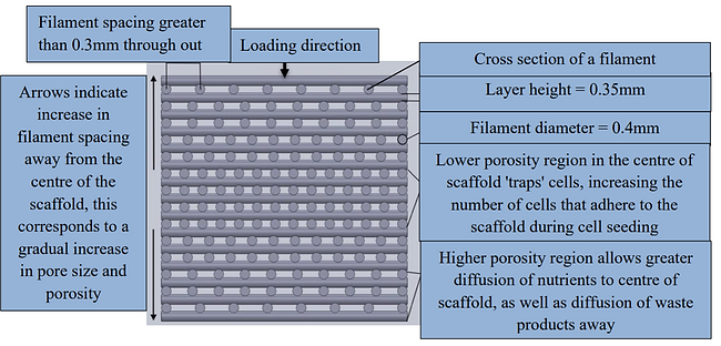
Porosity Gradient Scaffold Design Schematic

Porosity Gradient Scaffold Model - Solidworks
CFD Analysis
The third consideration was to have uniform flow across the entire scaffold. This was a concern because regions with excessively high flow compared to other regions can result in cell detachment. So, four different scaffold designs, consisting of a uniform scaffold design and three designs with increasing porosity gradients, were tested using a CFD package to verify this wouldn't be an issue. ANSYS Fluent was used for the CFD simulations.
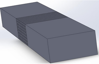
Symmetric Flow Domain - Solidworks
Simulation Setup and Meshing
First, I created a flow domain on Solidworks to emulate the chamber within which the scaffold would reside. Two cubic blocks were intersected with two opposite faces of the scaffold to create a flow domain, which was then cut in half at its centreline. In the symmetric fluid domain, the solid areas are where fluid can flow and the hollow areas can be considered as solid (the scaffold itself).

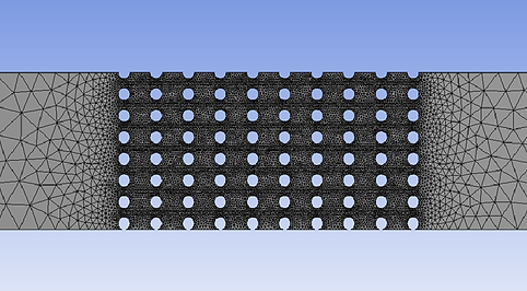
Symmetric Flow Domain Cross-section - Solidworks
The symmetric flow domain model was then exported to ANSYS Workbench, where it a mesh for it was created using the mesher. The mesh was designed to start off as coarse from the fluid domain's inlet and progressively become more refined towards the centre of it (where the scaffold is). A refined mesh was needed for the scaffold area as shear stress and pressure contours on the scaffold walls needed to be accurately simulated.

Flow Domain Mesh Isometric View - ANSYS Workbench Mesher
Flow Domain Mesh Side View - ANSYS Workbench Mesher
The symmetric flow domain model was then exported to ANSYS Workbench, where it a mesh for it was created using the mesher. The mesh was designed to start off as coarse from the fluid domain's inlet and progressively become more refined towards the centre of it (where the scaffold is). A refined mesh was needed for the scaffold area as shear stress and pressure contours on the scaffold walls needed to be accurately simulated.
Simulation Model and Results
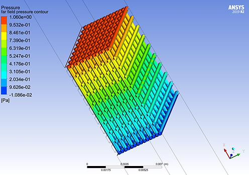
Once the flow domain was meshed, it was exported to ANSYS Fluent. A viscous-laminar fluid model was used as the flow rates through direct perfusion scaffolds are typically low. This meant that flow would be laminar throughout the flow domain and meet suitable cell culture growth criteria. Other input variables such as velocity, Reynold's number and pressure values were calculated and inputed into the model. The fluid properties were set to be the same as the culture medium that was selected for the bioreactor. I used three different types of post processing data to assess which type of scaffold would be best: Scaffold wall shear contours, scaffold stress contours and velocity streamlines.
Scaffold Stress Contour - ANSYS Fluent
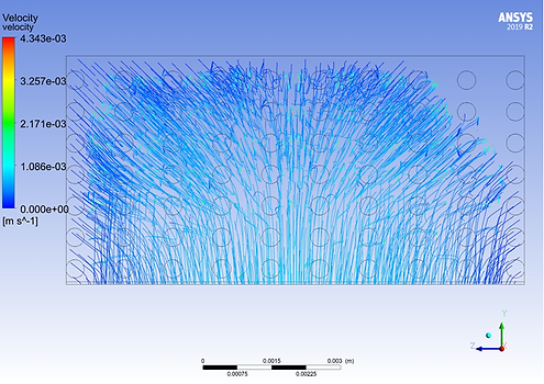
Velocity Streamlines Inlet View - ANSYS Fluent

Scaffold Wall Shear Contour - ANSYS Fluent
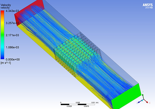
Velocity Streamlines Top View - ANSYS Fluent
The four different simulation cases were set to run for 100 iterations but they all converged at around 40. After analysing the results, it was found that the maximum gradient porosity scaffold performed best due to its suitable stress and shear values. Furthermore, the velocity streamlines were the most uniform across that scaffold, meaning that the fluid was dispersed more evenly than for the other scaffold designs.
System Flowchart
I also designed a flowchart of the entire system to show how it would function.
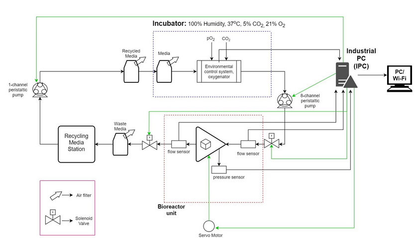
Bioreactor System Flowchart
Final Design
The render to the right (made by another team member) shows the final design of the bioreactor. The barrel would be filled with an incompressible fluid (most likely distilled water), and the piston would apply pressure to this water. This pressure would be applied to the membrane, which would deform and transfer the pressure to the scaffolds sitting within the scaffold holder. The square holes on the outside of the scaffold holder allow for square cross-section tubes to penetrate the scaffold holder. These tubes would allow for medium fluid to come in and pass through the scaffolds. The fluid would then leave through a tube coming out from below the bioreactor.
The engineering drawing below shows the whole assembly labelled.
Piston assembly

Barrel
Membrane
Medium fluid inlet
Scaffold holder
Bioreactor CAD Render - Solidworks

Bioreactor Assembly Engineering Drawing - Solidworks
Project Evaluation
Overall, the project was considered to be a success. We achieved all our objectives. Although the COVID pandemic affected the final part of the project which involved presenting to a mock tender board, this was ultimately done online. I personally learnt a lot from this project. I developed my leadership abilities, I developed my CAD modelling skills, I learnt how to do CFD simulations and most importantly, my interest in the biomedical engineering field was ignited.
I can provide the final report and testing information if requested.