

SMART Domestic Underfloor Flood Pump
Preventing In-home Underfloor Flooding

The SMART underfloor flood pump is a flood defence product that combats underfloor flooding in domestic properties. The pump design has innovative features such as a telescopic housing for height adjustment, an SMS alert system for owners and a battery switching system to provide an uninterrupted power supply.
As a result of this project, significant steps were made toward making the SMART pump a commercially viable product. As the project was partially sponsored by Eco Coverage Technologies Ltd, its commercial distribution may become a reality in the near future.
Client Organization
University of Southampton
Year
2019 - 2020
Supervisors
Prof. Martin Browne
Dr. Andy Taylor
Location
Southampton, UK
Team/Solo
Solo
Funding
GBP 100
Technologies Utilised
Fusion 360, Ultimaker Cura
Context
This project’s objective was to reduce the impact of groundwater flooding. It is estimated that around 4.72 million domestic properties in the UK are in areas at risk of groundwater flooding. While not as common as other sources of flooding, it can be equally as devastating; property damage can result in expensive repairs, contaminated water can flow into homes and lives can be lost. Groundwater flooding can lead to water seepage into the underfloor of domestic properties. Sump pumps are the existing countermeasure but they are very expensive, difficult to install and require frequent maintenance. The SMART-pump was designed to activate in emergencies and pump water out of the space under a property faster than it is flowing in. The final design was meant to be inexpensive, easy-to-fit, easy-to-maintain and automated. The SMART-pump is meant to be placed in an 80mm hole under a kitchen sink and touch the underfloor. This project aimed to optimise the base design by making the pump height adjustable, enabling usage for a range of underfloor heights, and by creating a battery-switching-system (BSS), which would allow automatic switching from mains power to a battery in the case of power failure.
Project Aims and Objectives
Aim
-
Optimise the design of the SMART-pump, manufacture it and then test it.
Objectives
-
Review base pump design and performance.
-
Conduct evaluation of pump applicability and commerical viability.
-
Change base design to improve pump efficiency and manfucture a prototype.
-
Re-design pump housing to allow for height adjustability.
-
Design a backup battery switching system to work with the pump's electronics.
-
Conduct a detailed CFD analysis for the pump housing.
-
Manufacture and test the re-designed pump with the backup battery switching system.
Project Work
This section highlights the notable work done during this project.
Initial Research and Analyses
At the start of the project, my supervisors confirmed that there was room to improve the pump. The most important improvments involved increasing its efficiency and making it height adjustable for different underfloor heights. Firstly, I conducted an analysis of soil properties to calculate average soil hydraulic conductivity (how well soil transmits water), and a study of UK domestic property distribution to calculate average underfloor areas. I then used the results of these to analyses in combination with other statistics to find the maximal rate of water inflow that the pump would have to be able to counter. I also researched sump pump systems to aid in my design process and conducted a study into underfloor height variaiblity for domestic propoerties in the UK to set limits on pump height adjustability.
Initial Pump Design
This section covers the pump's initial design. The pump was designed to fit within a hole in a test rig, which consists of two levels, each with one container. The pump sits within the lower container. Once this container is filled with water, the pump starts to pump water to the higher container.
The pump contains a float switch at the bottom section. Once the water level is high enough the float switch activates the pump, which starts evacuating the water from the region. The water then flows upward through an airtight pump housing made of perspex.
The primary issue with this design was that it was not efficient enough, nor was it adjustable in height. Most importantly, this design was not commercially viable.

SMART Pump Test Rig Design
New Pump Design
-
Discharge Pipe Connection - Where outlet pipe connects to discharge pipe.
-
Power Cable - Groups all wiring into XLR connecter input.
-
Endcap - Covers pump housing.
-
Flange - Fixes pump housing to floorboards and prevents moisture from escaping.
-
Floorboards - Base for flange to fix to.
-
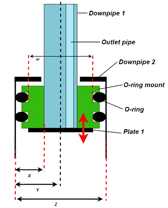
Downpipe 1 - Allows for height adjustment.
-
Outlet pipe - Allows for flow of water through housing.
-
Pump/float switch wiring - Connects hardware to power cable.
-
Downpipe 2 - Separated into two parts. Houses pump and float switch.
-
O-ring mount - Holds o-rings within its grooves, which allows for height adjustment and creation of a seal.
-
Plate 1 - Provides a base for o-ring mount to fix to.
-
Cable glands - Allows wiring to pass through housing whilst creating a seal.
-
Plate 2 - Plate to fix to outlet pipe and for wiring to pass through.
-
Vertical float switch - When the water level is high enough it activates the pump.
-
Bilge pump - Pump which generates water outflow.
-
Plate 3 - Fixes to downpipe 2 and bottom of bilge pump.
-
Filter - Prevents debris from entering pump housing and damaging system.

SMART Pump Design Schematic
Design Changes
Base Design
I made several design changes to make the pump more efficient. Firstly, I acquired a new bilge pump and cut off its outlet pipe to reduce frictional losses when pumping out water. I then re-designed the lower part of the pump housing to be more airtight, using cable glands for wires to pass through different sections. All perspex was cut using a bandsaw machine or laser cutting machine. The housing was attached together by using industrial grade acrylic cement and clamping all sections together. All wiring was soldered and sealed by hand.
Additional Fittings
Using Fusion 360, I designed three new parts to fit into the pump housing.
Wiring hole
Outlet pipe hole


Holes for pump screw
Slits to filter debris

Countersunk screw hole
Space for downpipe 1
Endcap
Designed to fit on top of the pump housing. Attaches to downpipe 1. Has two holes, one for wiring and one for the outlet pipe.
Filter
Designed to fit at bottom of pump housing and to bottom of bilge pump. Has holes that allign with holes under bilge pump for screws to fit into. Has slits for filtering debris.
Flange
Fixes the pump housing to floorboards. Sits beneath the endcap. Has two pieces that fix together using an interference fit.
Height Adjustable Mechanism
The most innovative part of the new pump design was the height adjustable mechanism. It was a difficult problem to tackle, as making something height adjustable whilst maintaining a water tight seal is not easy. I took inspiration from telescopic tubes, and arranged the housing so that downpipe 1 had a smaller diameter than downpipe 2, allowing it to slide in. I then designed an o-ring mount that would be attached to the outside of downpipe 1, with o-rings creating a seal between the downpipes whilst allowing them to slide in and out of each other.
I had to create a reciprocating dynamic seal, similar to a moving rod and piston. After making the necessary calculations for the o-ring dimensions, I selected a suitable nitrile butadiene rubber o-ring.
Once the o-ring was selected, I then had to design the o-ring mount. To create an effective reciprocating seal, I had to find the necessary groove dimensions for the o-ring mounts grooves. This involved several complex calculations which required consultation of groove design manuals.
Since I was going to be manufacturing the o-ring mount using my personal 3D printer, I had to account for the tolerance of the printer. Since groove dimensions had to be precise to create an effective seal, I knew it would be a long process to get the right piece. Therefore, I created an excel worksheet with all the groove design variables in it. All the variables were coupled to each other with equations, allowing me to try out several different combinations to attain the best result.
Prototyping and Manufacturing
During this stage of the project, I used my 3D printer (Anycubic Mega X) to manufacture the components I designed. I used Ultimaker Cura to slice the CAD files into 3D printable file formats. With this software, I could change variables such as nozzle temperature, print bed temperature, print speed, infill percentage, layer height, use of support and use of adhesion, all depending on the requirement of the part and the filament material. I followed a protoyping process to ensure I stayed on track.
Height Adjustable Mechanism Schematic

o-ring grooves
O-ring Mount CAD Render - Fusion 360

Prototyping Process
The hardest part to print was the o-ring mount due to the 3D printers tolerance. I manufactured around ten to fifteen versions until I finally found the perfect groove dimensions. I also managed to print the flange, which required two to three different versions until the interference fit was suitable.


Final Flange Prototype
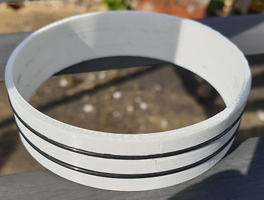
Final O-ring Mount Prototype
Once the flange and o-ring mount were printed, I had to test whether they fit with the downpipes. Once confirmed that they did fit, I commenced some simple testing to see if the seal worked. I did this by filling a tub with water and putting the pump housing into it. The seal was water-tight whilst allowing for height adjustment.
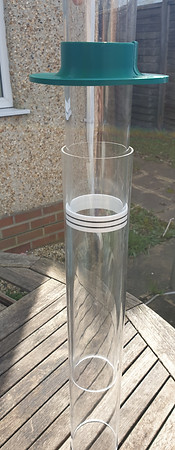
O-ring mount, flange and downpipes
Battery Switching System (BSS)
I decided that the SMART pump also needed a battery switching system (BSS). This was important because flooding can cause power outages, which would prevent the pump from working in such scenarious. The BSS design used the LTC4412 Low Loss PowerPath Controller as its primary component. I found several configurations to use this controller in, one of which was perfect for the BSS (shown on the right).

LTC4412 Automatic Switchover Circuit
Engineering Drawings
I also made several engineering on Fusion 360 in order to allow any future project teams to manufacture the parts I designed. Some of these are shown below.

O-ring Mount Drawing - Fusion 360
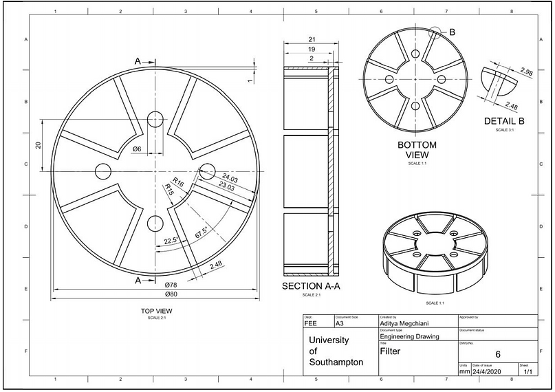
Filter Drawing - Fusion 360
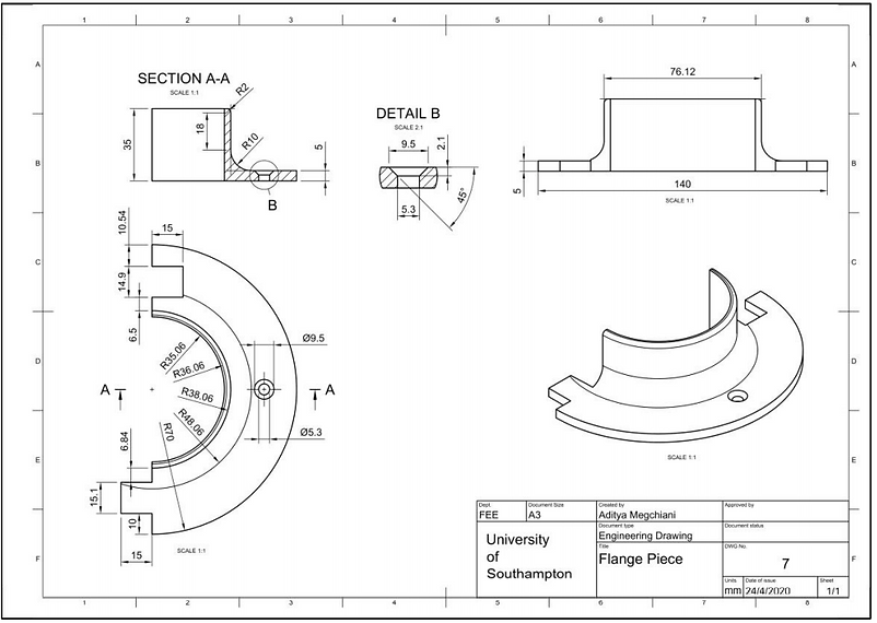
Flange Drawing - Fusion 360
Project Evaluation
Overall, the project was not considered to be a success. Due to the emergence of the COVID pandemic, my university had closed halfway through the second semester. This prevented me from manufacturing and testing a complete prototype and the BSS. Furthermore, I was unable to run CFD simulations for the pump housing to test its potential efficiency. However, I was able to create designs and guides that would further the project in the future. The designs included several different variations of the BSS to test and instructions on how to design the o-ring mount for further variation. The guides included set-up procedures for consumers, details of testing that would need to be conducted in the future, certifications that would need to be attained in the future and any additional work that would improve the product in areas it is lacking.
I also learnt many vital skills and lessons such as undertaking a whole project on my own, creating CAD assemblies/renders, 3D printing intricate parts, and groove/seal design methodology. Sadly, I was not able to see the project through to the end and create a prototype of a potentially comercially viable product.
I can provide the final report and testing information if requested.
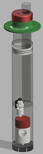
Smart Pump Assembly CAD Render - Fusion 360